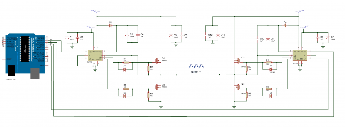
Full Bridge Mosfet Driver
H-Bridge MOSFETs Diodes Incorporated’s’ line of MOSFET H-Bridges optimize the design of DC motor control and inverter circuits. With a simplified design, one Diodes MOSFET H-Bridge can replace two dual SO’s, reducing: PCB area footprint by 50%, component count and PCB area, and overall cost.
Structure of an H bridge (highlighted in red) H bridges are available as, or can be built from. The term H bridge is derived from the typical graphical representation of such a circuit.
S oft ware ini m encakup Analisa Model Struktur secara Menyeluruh untuk dapat melakukan P erancang an, Analis a, P erm odelan bah kan Simul asi s uat u kond isi Bangunan. The Sky is The Limit adalah Konseptual utama dalam mempelajari Program ini, Bagi seorang Engineer Sipil dengan Konseptual yang sama pada Software ini maka kecenderungan untuk menguasai Software lain akan sama mudahnya. Rogram With G UI atau lebih dikenal deng an S AP 20 00 ad alah salah s atu Softwar e Analis a S tr ukt ur yan g cukup diken al d i Kalangan Teknik S ipil. Belajar sap 2000 pdf.
An H bridge is built with four switches (solid-state or mechanical). When the switches S1 and S4 (according to the first figure) are closed (and S2 and S3 are open) a positive voltage will be applied across the motor. By opening S1 and S4 switches and closing S2 and S3 switches, this voltage is reversed, allowing reverse operation of the motor. Using the nomenclature above, the switches S1 and S2 should never be closed at the same time, as this would cause a short circuit on the input voltage source.
The same applies to the switches S3 and S4. This condition is known as shoot-through. Operation [ ].
The two basic states of an H bridge The H-bridge arrangement is generally used to reverse the polarity/direction of the motor, but can also be used to 'brake' the motor, where the motor comes to a sudden stop, as the motor's terminals are shorted, or to let the motor 'free run' to a stop, as the motor is effectively disconnected from the circuit. The following table summarises operation, with S1-S4 corresponding to the diagram above. S1 S2 S3 S4 Result 1 0 0 1 Motor moves right 0 1 1 0 Motor moves left 0 0 0 0 Motor coasts 1 0 0 0 Motor coasts 0 1 0 0 Motor coasts 0 0 1 0 Motor coasts 0 0 0 1 Motor coasts 0 1 0 1 Motor brakes 1 0 1 0 Motor brakes 1 1 0 0 Short circuit 0 0 1 1 Short circuit 0 1 1 1 Short circuit 1 0 1 1 Short circuit 1 1 0 1 Short circuit 1 1 1 0 Short circuit 1 1 1 1 Short circuit Construction [ ]. L298 dual H bridge motor Relays [ ] One way to build an H bridge is to use an array of from a relay board.
A ' (DPDT) relay can generally achieve the same electrical functionality as an H bridge (considering the usual function of the device). However a semiconductor-based H bridge would be preferable to the relay where a smaller physical size, high speed switching, or low driving voltage (or low driving power) is needed, or where the wearing out of mechanical parts is undesirable.
Another option is to have a DPDT relay to set the direction of current flow and a transistor to enable the current flow. This can extend the relay life, as the relay will be switched while the transistor is off and thereby there is no current flow. It also enables the use of PWM switching to control the current level.
N and P channel semiconductors [ ] A H bridge is typically constructed using opposite polarity devices, such as PNP (BJT) or P-channel connected to the high voltage bus and NPN BJTs or N-channel MOSFETs connected to the low voltage bus. N channel-only semiconductors [ ] The most efficient MOSFET designs use N-channel MOSFETs on both the high side and low side because they typically have a third of the ON resistance of P-channel MOSFETs. This requires a more complex design since the gates of the high side MOSFETs must be driven positive with respect to the DC supply rail. Many integrated circuit MOSFET include a within the device to achieve this.
Alternatively, a DC–DC converter can be used to provide isolated ('floating') supplies to the gate drive circuitry. A multiple-output flyback converter is well-suited to this application. Another method for driving MOSFET-bridges is the use of a specialised transformer known as a GDT (Gate Drive Transformer), which gives the isolated outputs for driving the upper FETs gates. The transformer core is usually a ferrite toroid, with 1:1 or 4:9 winding ratio. However, this method can only be used with high frequency signals. Cityengine keygen software. The design of the transformer is also very important, as the should be minimized, or cross conduction may occur.
The outputs of the transformer are usually clamped by, because high could destroy the MOSFET gates. Variants [ ] A common variation of this circuit uses just the two transistors on one side of the load, similar to a. Such a configuration is called a 'half bridge'. The half bridge is used in some switched-mode power supplies that use and in. The half-H bridge type is commonly abbreviated to 'Half-H' to distinguish it from full ('Full-H') H bridges. Another common variation, adding a third 'leg' to the bridge, creates a three-phase inverter.
- пятница 02 ноября
- 72